Does DOM/DDM Prove Optical Transceiver Compatibility?
Learn what DOM/DDM readings can verify, what they cannot prove, and how to use optical diagnostics in a defensible transceiver compatibility review.
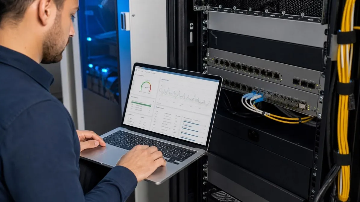
No. Readable digital optical monitoring (DOM), also called digital diagnostic monitoring (DDM), proves that the host can access supported diagnostic data from the installed transceiver in that particular port and software state. It does not prove complete optical transceiver compatibility.
DOM/DDM is useful evidence. It can show current transmit power, receive power, temperature, supply voltage and laser bias current when those fields are supported. Engineers can use the readings to establish a baseline, check module alarms and narrow the fault domain.
But a compatible deployment must answer additional questions: Does the host accept the module? Is the port configured correctly? Do both optical endpoints match? Are forward error correction (FEC), breakout and lane settings correct where applicable? Does the link pass traffic without unacceptable errors? DOM/DDM cannot answer all of those questions by itself.
What DOM/DDM Actually Monitors
The SNIA SFF-8472 specification defines a management interface used by many SFP-family modules. It describes diagnostic information, calibration methods, warning and alarm thresholds, and how supported data is presented through the module's management memory.
For newer or different form factors, the management specification and available diagnostics can differ. This article uses DOM/DDM as the familiar operational term, but the exact fields must always be checked for the transceiver and host under review.
When supported and exposed by the platform, the most familiar readings are:
| Reading | What it can tell you |
|---|---|
| Transmit optical power | The module-reported optical output at the local transmitter. It can be compared with the approved transmit range for the exact optic. |
| Receive optical power | The module-reported optical power arriving at the local receiver. It can help identify weak, absent or unexpectedly strong input. |
| Module temperature | The temperature measured inside the module. It is not automatically the same as rack or room temperature. |
| Supply voltage | The voltage reported at the transceiver. An abnormal value can support a wider module, port or host power investigation. |
| Laser bias current | The current used to drive the transmitter laser. It can be useful as a baseline or trend, but it is not a stand-alone health verdict. |
These are module-reported operating values. They are not a substitute for an external optical power meter, a bit-error-rate test, traffic monitoring or a platform compatibility record when those forms of evidence are required.
What Readable DOM/DDM Proves—and What It Does Not
If a host displays credible DOM/DDM data, several things have happened: the module is present, at least part of the management interface is readable, and the host software can present supported telemetry.
That is more evidence than physical insertion alone. It is still only one compatibility layer.
| Readable DOM/DDM can support | It cannot prove by itself |
|---|---|
| The host can read supported diagnostic fields in the current configuration | The host supports every function of the module |
| Current module and optical operating values | Correct coding for every platform feature or software release |
| Comparison with the exact module's documented limits | Correct port speed, FEC, breakout or lane configuration |
| A before-and-after baseline during a controlled change | Optical interoperability with an incorrectly matched remote optic |
| Warning or alarm evidence for a wider investigation | Stable traffic, recovery behavior or long-term field operation |
A host may read the module identity and diagnostics while still applying an unsupported-transceiver policy. It may also accept the module and show normal-looking telemetry while the interface remains down because of port configuration, remote-end selection or an optical mismatch.
If the host reports an unsupported or rejected module, use the separate unsupported-transceiver warning workflow. Do not treat DOM visibility as a way to bypass platform support requirements.
Avoid Generic “Normal” DOM/DDM Ranges
A generic table of “good” optical power, temperature or bias values can be misleading. Acceptable limits vary by transceiver type, optical application, reach class, wavelength, temperature grade and implementation.
Compare the reading with three controlled references:
- The exact transceiver specification. Use the documented transmit-power range, receiver sensitivity, maximum receiver input, temperature range and other applicable limits for the precise part number or verified product identity.
- The module's warning and alarm thresholds. Treat these as module-specific diagnostic boundaries, not as universal link-design limits.
- The host's official presentation and support documentation. Confirm how the platform reports calibrated values, unavailable fields, warnings and alarms for the installed software release.
Do not copy an Rx-power threshold from a 10G LR module and apply it to a 25G BiDi, 100G LR4 or CWDM optic. Do not calculate engineering margin from nominal reach alone.
For a single-fiber deployment example, the 10G BiDi 40km guide explains why complementary wavelengths, receiver overload and the actual optical path still matter alongside DOM/DDM readings.
How to Interpret the Five Common Readings
Transmit power: useful, but not an independent measurement
Transmit power helps confirm that the local module reports optical output. Compare it with the approved range for that exact module.
An unusual value can justify further checks, but the reading alone does not identify the cause. Module calibration, host presentation, temperature, transmitter condition and the specific optical design may all affect interpretation. Use an appropriate external measurement when the project requires independent verification.
Receive power: evidence of arriving light, not a fault location
Receive power is often the most useful first measurement during turn-up. A low or absent reading can be consistent with excessive path loss, contamination, a disconnected path, an inactive remote transmitter, incorrect polarity or a mismatched BiDi wavelength direction.
It does not tell you which of those conditions is responsible. Compare both endpoints, inspect the path and change one verified variable at a time.
An unexpectedly high reading also matters. Long-reach optics on a short low-loss route can create receiver-overload risk. Check the exact maximum receiver input rather than assuming that stronger light is always better.
Temperature: module condition, not room temperature
DOM/DDM reports the temperature measured inside the transceiver. Airflow, port density, host design, adjacent modules and ambient conditions can influence it.
Use the exact operating-temperature class and module thresholds. A warm module is not automatically defective, and a value within the permitted range does not prove that the entire link is compatible.
Supply voltage: one part of a wider power check
Supply-voltage telemetry can help identify an abnormal operating condition. If several modules on the same host show unusual values, the investigation may need to include the chassis, port or power environment rather than replacing every optic.
Record the pattern and compare with the exact transceiver limits. Do not diagnose a failed module from voltage telemetry alone.
Laser bias current: most useful with context and trends
Bias current can support a transmitter-health investigation when compared with the module's thresholds, temperature and historical baseline. A changing value may deserve attention, but there is no universal bias-current limit for all optics.
Use it as supporting evidence. Do not convert one bias reading into an unsupported remaining-life or failure prediction.
Missing or Zero DOM/DDM Is Not Automatic Proof of Failure
A module can be detected while one or more diagnostic fields are unavailable, shown as not applicable or displayed unexpectedly. Possible reasons include:
- The module does not implement the requested diagnostic function.
- The host, line card or software release does not expose that field.
- Monitoring is disabled or requires a platform-specific configuration.
- The management interface, coding or calibration data is not being interpreted as expected.
- A value is not applicable to that module architecture or operating state.
- The module or port may have a genuine fault that still requires isolation.
Start with the exact host model, line card, software release and official command reference. Cisco, HPE Aruba Networking and Juniper documentation all show that available commands, displayed fields and supported optics depend on the platform.
Do not use one vendor's CLI command as a universal procedure. Do not replace a transceiver solely because another device displays more diagnostic fields.
Put DOM/DDM in the Compatibility Evidence Chain
A defensible compatibility review separates different questions instead of using one signal as the final verdict.
| Evidence layer | Question it answers |
|---|---|
| Product identity and specification review | Is this the correct form factor, rate, optical application, wavelength, connector and reach class for the documented requirement? |
| Host recognition and policy | Does the exact host, line card and software release identify and permit the module? |
| DOM/DDM visibility | Can the platform access the required diagnostic values and alarms in this configuration? |
| Port and optical validation | Do the speed, FEC, breakout, lanes, remote optic, fiber path and optical power conditions fit the deployment? |
| Controlled operational validation | Does the documented configuration establish link, pass the required traffic checks and behave acceptably under the defined test conditions? |
| Field evidence | Has operation been confirmed in the actual deployment, without extending that result to untested environments? |
Readable DOM/DDM belongs in the third layer. It strengthens the evidence package but cannot replace the other layers.
Before ordering, use the optical transceiver compatibility-check guide to collect the host, port, software, fiber and validation information required for the wider review.
A Practical DOM/DDM Review Workflow
Use this sequence during commissioning, troubleshooting or sample validation:
- Record the exact environment. Capture the host vendor and model, line card or network interface card where applicable, software version, port identifier, speed, FEC and breakout mode.
- Identify both transceivers. Record complete part numbers, optical applications, wavelengths and coding requirements for End A and End B.
- Preserve the original state. Save interface status, alarms, error counters and available DOM/DDM values before reseating, recoding or replacing anything.
- Read both ends. Compare local Tx with remote Rx and remote Tx with local Rx where supported. For multi-lane optics, review the relevant lanes rather than one summary value.
- Use exact limits. Compare the data with approved documentation for the precise modules and with the host's official interpretation.
- Check the non-DOM layers. Confirm host acceptance, port mode, FEC, lane mapping, remote-end selection, fiber type, polarity, BiDi wavelength pairing and passive components.
- Change one variable at a time. Clean, reconnect or substitute one controlled component, then capture the readings again.
- Record the decision boundary. State what the evidence supports and what still requires a sample, controlled test or field confirmation.
This workflow makes the inquiry more useful. Instead of “DOM looks normal,” the engineering record describes the exact environment, measurements, limits, configuration and remaining uncertainty.
What to Send for a DOM/DDM Compatibility Review
Prepare the following information before requesting support:
- Host vendor and complete model at both endpoints
- Line card, network adapter or sub-module where applicable
- Software or firmware version
- Port identifier, configured speed, FEC and breakout mode
- Full transceiver part number and coding requirement at both ends
- Exact warning, alarm or link symptom
- Fiber type, connector, distance and passive components
- Wavelength or optical application at both ends
- DOM/DDM output from both endpoints, including units and thresholds where shown
- Interface error counters and link state
- Results of any controlled cleaning, reconnection or known-good substitution
- Required evidence level before rollout
For backhaul projects, the ISP/WISP backhaul optics page provides the wider solution context. The final optics decision still needs the actual host, optical path and validation requirements.
Frequently Asked Questions
Are DOM and DDM the same thing?
They are commonly used as alternate terms for transceiver diagnostic monitoring. Vendor documentation may prefer one term, and the underlying management specification can vary by form factor and module generation. Check the exact host and transceiver documentation rather than relying on the label alone.
Does readable DOM/DDM prove that a third-party transceiver is compatible?
No. It shows that the host can access supported diagnostic data in that port and software state. Complete compatibility can also require host acceptance, correct coding, port configuration, optical matching, traffic checks and deployment-specific validation.
Why can the host detect the module but show no DOM/DDM values?
Identification and diagnostic monitoring are separate capabilities. The module may not implement the field, the host or software may not expose it, monitoring may require configuration, or the data may not be interpreted as expected. Check official platform documentation before diagnosing a failed optic.
Can I use generic Tx and Rx power ranges from another SFP?
No. Compare readings with the approved limits for the exact transceiver. Optical power windows differ by application, reach, wavelength and design. Generic ranges can hide receiver overload or incorrectly classify a valid reading as a fault.
Does low receive power prove the local transceiver is defective?
No. Low Rx power means that the local receiver reports weak incoming light. The cause can be the remote transmitter, connector contamination, excessive path loss, a disconnected route, incorrect polarity or a mismatched optical endpoint. Use both-end measurements and controlled isolation.
Can DOM/DDM replace an optical power meter or traffic test?
No. DOM/DDM is module-reported telemetry. It is valuable for monitoring and troubleshooting, but an independent optical measurement or controlled traffic test may still be required by the project's validation plan.
What should I send Axonode before asking whether the readings are acceptable?
Send both host models, software versions, port settings, exact transceiver part numbers, fiber and distance information, the complete DOM/DDM output with units and thresholds, current link state and any alarms or error counters. This allows the readings to be reviewed against the actual deployment rather than a generic table.
Use DOM/DDM as Evidence, Not a Shortcut
DOM/DDM is one of the most useful sources of optical-link evidence available from the host. Its value comes from context: the exact module, exact platform, exact limits, both endpoints and a controlled record of what changed.
Readable values do not prove complete compatibility. Missing values do not prove module failure. Use the telemetry to narrow the question, then complete the host, port, optical and operational checks required for the deployment.
Need help reviewing compatible optics or an uncertain DOM/DDM result? Send Axonode the equipment models, software versions, port settings, current transceiver part numbers, link details and diagnostic output from both endpoints. We can help organize the requirements and identify what can be concluded from the available evidence—and what still needs controlled validation.