Optical Transceiver Selection, Compatibility and Deployment Guide
Plan optical transceiver selection, host compatibility, link budget, validation, BOM preparation, installation and troubleshooting for network projects.
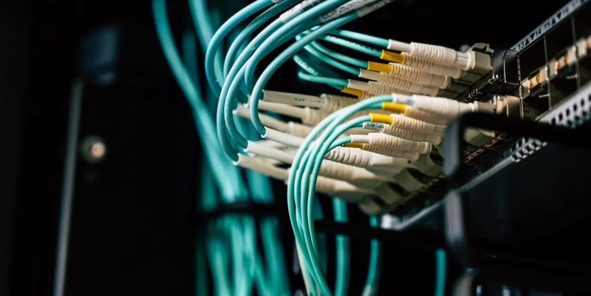
Select an optical transceiver from the complete deployment requirement, not from data rate and distance alone. A reliable choice aligns the host port, software, form factor, fiber plant, connector, topology, wavelength plan, optical budget and operating environment.
This guide gives ISPs, WISPs, system integrators and enterprise network teams a practical path from the first port audit to an acceptance-ready bill of materials (BOM). It is a planning framework, not a universal compatibility claim.
01Identify the Deployment Requirement
Start with both endpoints and the installed route. “10G, 40 km” is not enough to identify a module.
Record:
- host vendor, chassis or appliance, line card or network adapter and exact port;
- software or firmware version, intended port speed, breakout mode and Forward Error Correction (FEC) setting;
- route length, fiber type, connector, polarity, patch panels, splices and passive devices;
- duplex, bidirectional (BiDi), coarse wavelength-division multiplexing (CWDM), dense wavelength-division multiplexing (DWDM) or parallel-fiber topology;
- environment, temperature range and any host power or thermal restrictions;
- monitoring requirements, quantity by variant, spare quantity and deployment schedule.
Document uncertainty instead of filling a BOM with assumptions. The published optical transceiver upgrade checklist provides a field-by-field audit format.
02Select the Data Rate and Form Factor
The port controls which electrical interface and mechanical form factor can be used. A module that fits physically may still have the wrong electrical lane arrangement, signaling mode or host configuration.
Check the required Ethernet rate, supported form factor, lane count, breakout mapping and FEC behavior. For higher-power modules, also confirm the host port’s documented power and thermal limits.
Do not assume that a faster optic can operate at a lower rate or that every QSFP-family port supports every breakout mode. Confirm the exact host and software combination.
03Plan Reach and Optical Budget
Nominal reach is a product-class reference, not a substitute for a link calculation. Start with the verified minimum transmit power and receiver sensitivity for the exact module. Then account for the installed path.
| Budget item | What to verify |
|---|---|
| Available optical budget | Minimum transmit power minus receiver sensitivity, using the same conditions and units |
| Route loss | Fiber attenuation for the actual wavelength and route length |
| Passive loss | Connectors, splices, patch panels, splitters, mux/demux units and other passive components |
| Engineering allowance | Aging, contamination, repairs, measurement uncertainty and other project-specific margin |
| Receiver overload | Maximum receive power, especially on short paths or high-output optics |
The remaining margin must stay positive under the project’s accepted assumptions. Long-reach and wavelength-multiplexed links may also require dispersion or other signal-integrity checks. Use the ISP backhaul optical loss-budget checklist for a more detailed workflow.
04Verify Fiber Type, Connector and Polarity
Match the module to the installed fiber: single-mode fiber (SMF) or the documented multimode-fiber (MMF) grade. Confirm the connector at the module and every transition in the path.
Duplex LC, simplex LC, MPO/MTP and other interfaces are not interchangeable. Parallel optics also require the correct fiber count and polarity method. Inspect and clean connector end faces before concluding that a module or coding profile is faulty.
05Choose Duplex, BiDi, CWDM or DWDM
Topology determines the endpoint optics and the fiber plan.
| Option | Typical decision value | Checks that cannot be skipped |
|---|---|---|
| Duplex optics | Straightforward point-to-point links using separate transmit and receive fibers | Fiber type, connector, wavelength class, budget and endpoint interoperability |
| BiDi optics | Adds capacity when only one fiber strand is available | Complementary transmit/receive wavelengths at opposite ends, simplex path and budget in both directions |
| CWDM | Carries several wavelength channels over a shared fiber path | Channel plan, mux/demux ports, insertion loss, endpoint wavelengths and upgrade space |
| DWDM | Supports denser channel plans and more advanced transport designs | Exact channel/frequency, passive or active line system, power, dispersion and operating controls |
BiDi modules are purchased and deployed as complementary endpoint pairs. Never place two modules with the same transmit/receive orientation at opposite ends. The fiber-capacity expansion guide compares BiDi, CWDM and DWDM planning in more detail.
06Confirm Host Compatibility and Coding
Compatibility is specific to a host vendor, device, line card or adapter, port mode and software version. Identify the required coding or reference part number for each endpoint.
Correct coding may allow the host to recognize the module and expose expected identification data. It does not by itself prove that the fiber, wavelength plan, optical budget, FEC, breakout configuration or remote endpoint is correct.
Use the published optical transceiver compatibility check to separate product identity, coding evidence and deployment validation.
07Understand DOM/DDM and Validation Limits
Digital optical monitoring or digital diagnostics monitoring (DOM/DDM) can expose values such as module temperature, supply voltage, laser bias current, transmit power and receive power when both the module and host support them.
These readings help establish presence, visibility and current optical conditions. They do not prove future software support, interoperability under every load, or long-term reliability. A healthy reading can coexist with the wrong wavelength pair, insufficient margin, intermittent fiber loss or a configuration problem.
See Does DOM/DDM Prove Optical Transceiver Compatibility? for the evidence boundary.
08Use Sample and Small-Batch Validation
Use a representative sample when the host/software combination, coding profile, topology or environmental condition has not already been verified for the project.
Define pass/fail criteria before ordering the sample:
- correct module recognition and inventory fields;
- expected speed, FEC and breakout operation;
- stable link at both endpoints;
- DOM/DDM visibility where required;
- receive power and margin within the accepted link plan;
- clean error counters during the agreed observation period;
- restart, reseat or failover behavior relevant to the deployment.
A sample result applies to the tested configuration. Treat a platform, line-card, software, fiber or endpoint change as a new validation variable.
09Build a Deployment-Ready Optics BOM
A usable BOM maps every optic to a port and endpoint. It also preserves the information needed for coding, purchasing, installation and later replacement.
| BOM field | Purpose |
|---|---|
| Site and endpoint | Prevents modules from being assigned to the wrong side of the link |
| Host, card and port | Defines the compatibility target |
| Rate, form factor and interface | Defines the electrical and mechanical requirement |
| Fiber, connector and route | Defines the physical path |
| Wavelength pair or channel | Controls BiDi and WDM assignment |
| Reach and budget reference | Records why the optic fits the path |
| Coding and monitoring requirement | Controls host recognition and operational visibility |
| Quantity, spares and phase | Supports procurement and rollout planning |
Freeze the approved BOM revision before bulk ordering. Record any later substitution, coding or wavelength change rather than silently replacing a line item.
10Complete Installation and Acceptance Checks
Before installation, compare labels and quantities with the approved BOM. Clean the fiber, confirm polarity and record the initial host configuration.
- Confirm that both endpoints identify the intended module and port mode.
- Verify link state, negotiated or configured speed, FEC and breakout mapping.
- Record transmit/receive power, alarms and thresholds where available.
- Compare the readings with the planned budget and the remote endpoint.
- Review interface errors and stability during the agreed acceptance period.
- Save the baseline, module identity and final configuration for future troubleshooting.
11Troubleshoot in a Controlled Order
Avoid replacing multiple variables at once. Start with the symptom and isolate the layer.
| Symptom | First checks |
|---|---|
| Module not recognized | Exact host/port support, coding, software, seating and known-good port |
| Module recognized but no link | Speed/FEC/breakout, fiber polarity, cleanliness, remote optic and wavelength pairing |
| Low receive power | Route loss, connectors, splices, mux/demux loss, transmitter output and bends |
| High errors or unstable link | Margin, contamination, temperature, FEC, remote endpoint and intermittent path loss |
| DOM/DDM unavailable | Host and module monitoring support, software command, port state and coding profile |
Record each change and its result. A controlled comparison with a known-good port, patch cord or module is more useful than replacing the entire link at once.
12Frequently Asked Questions
Can I select an optic from speed and distance alone?
No. Speed and nominal reach do not confirm the form factor, host support, fiber, connector, wavelength topology, optical budget, FEC or operating environment.
Does correct coding guarantee a working link?
No. Coding can support host recognition, but the complete deployment still depends on configuration, fiber, wavelength, budget, endpoint interoperability and software behavior.
Is a higher-reach module always safer?
No. It may have different power, cost, receiver-overload or host-support constraints. Select from the calculated path and the exact host rather than adding reach without review.
What must be checked for a BiDi link?
Confirm complementary transmit/receive wavelengths at opposite endpoints, the simplex fiber path, connector, route loss and optical budget in both directions.
When should I request a sample?
Use a sample or pilot batch when a critical host, software, coding, topology or environmental variable has not been validated for the intended deployment.
What should I send Axonode for a BOM review?
Send the host and port list, software versions, rate and form factor, fiber and connector, route length and loss information, topology or wavelength plan, monitoring requirement, quantity and schedule.
Review a Deployment Requirement
Share the endpoint hosts, port modes, software versions, fiber route, connector, topology, required reach, available loss data, quantity and schedule. Axonode can help normalize the requirement, identify open validation points and prepare a project-specific optics BOM.
Review a deployment requirement