25G BiDi Upgrade Planning: Pairing, FEC, Fiber Path and Host Checks
Plan a 25G BiDi upgrade by checking SFP28 port support, complementary wavelengths, FEC, fiber loss, host compatibility and validation before ordering.
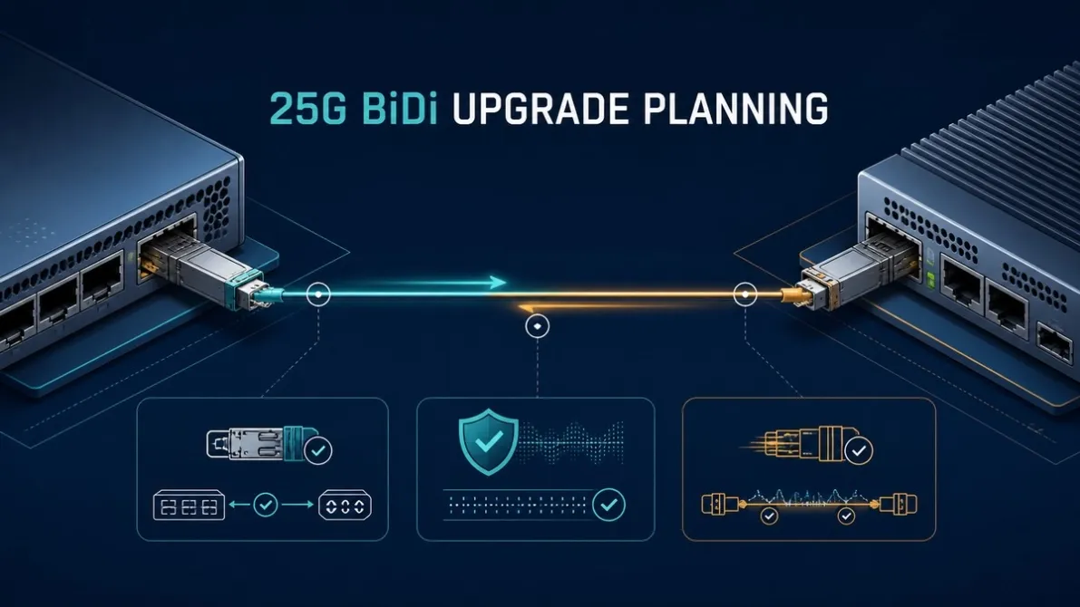
A 25G BiDi upgrade is not a simple swap from an SFP+ module to an SFP28 module. It is a link migration involving two host ports, two complementary transceivers, one fiber path and a shared physical-layer configuration.
Before ordering, confirm that both endpoints can run the intended 25G mode, the BiDi wavelengths are complementary, the installed fiber route fits the selected optical power window, and the Forward Error Correction (FEC) behavior is supported at both ends. If any one of these items is assumed rather than checked, a mechanically correct module can still produce a rejected, unstable or down link.
Start With a 25G Link Decision, Not a Module Search
First define what the upgrade must achieve. Is the objective to increase one 10G backhaul link to 25G, release a second fiber strand, replace a leased circuit, or standardize several edge sites?
The answer determines whether 25G BiDi is a suitable topology. A single-fiber BiDi pair can carry transmit and receive traffic over one strand by using two wavelengths. It is useful when a point-to-point route has one suitable single-mode fiber available. It does not create additional channels on that strand in the way a CWDM or DWDM system can, and it does not resolve a host that lacks 25G port capability.
Use this early decision table before selecting a reach or coding profile.
| Planning question | Go/no-go evidence |
|---|---|
| Do both endpoints support 25G on the intended ports? | Exact host, line card or NIC, port number, software or firmware and supported port mode |
| Is one continuous strand available end to end? | Route record, patch-panel path, connector type and continuity test |
| Can both ends use complementary BiDi modules? | Verified End A and End B TX/RX identities from one approved product pair |
| Is the route inside the optical operating window? | Selected module limits compared with measured or defensibly estimated route loss |
| Are FEC requirements understood? | Supported FEC mode for the exact host, software and selected optical interface at both ends |
| Can the change be validated before rollout? | Representative hardware, test link, acceptance criteria and rollback plan |
If the answer to the first three questions is unknown, the project is not ready for an optics bill of materials (BOM).
Confirm That Both Ports Can Actually Run 25G
SFP+ and SFP28 modules have similar physical dimensions, but a shared mechanical form does not prove that a port supports both 10G and 25G operation. Check the exact switch, router or network interface card rather than relying on the shape of the cage.
Record the following for both endpoints:
- •host vendor and full model;
- •line card, daughter card or NIC where relevant;
- •exact port number or port group;
- •current software, firmware and driver version;
- •supported speed and media type on that port;
- •configured speed, autonegotiation and breakout state;
- •supported FEC modes;
- •transceiver coding or qualification policy;
- •environmental requirements at the installation site.
Port capability can vary within the same chassis. It can also depend on a particular line card, software release or port-group configuration. Do not convert a 10G BOM to 25G by changing only the module descriptions.
For a broader host and software intake process, use the optical transceiver compatibility check guide.
Treat the Two BiDi Modules as One Controlled Pair
A BiDi link requires complementary transmit and receive wavelengths. The transmitter at End A must match the receiver at End B, and the transmitter at End B must match the receiver at End A.
The pairing rule is:
| Endpoint | Required optical identity |
|---|---|
| End A | TX wavelength λ1 / RX wavelength λ2 |
| End B | TX wavelength λ2 / RX wavelength λ1 |
For example, one verified 25G family may use 1270 nm TX / 1330 nm RX at one end and 1330 nm TX / 1270 nm RX at the other. That is an example of complementary direction, not a universal wavelength rule for every reach or product family.
Do not order two modules because their headline descriptions both say “25G BiDi.” Confirm the exact module identity, direction and mate. The wavelength plan can change between reach classes and designs, so a module from one pair must not be mixed with a different pair based on a similar label.
A deployment BOM should list End A and End B separately. It should also preserve the direction on box labels, site records and spare-stock locations.
Audit the Single-Fiber Path End to End
Confirm the installed route before using the distance printed in a product name. The route should identify:
- •fiber type and approximate length;
- •the single strand assigned to the link;
- •connector type and patch-cord arrangement;
- •every patch panel, splice and cross-connect;
- •any splitter, filter or other passive component;
- •measured end-to-end loss when available;
- •site temperature and enclosure conditions;
- •maintenance ownership and access restrictions.
Nominal distance is a product selection category, not a guaranteed route allowance. The working decision comes from the selected pair's minimum transmit power, receiver sensitivity, maximum receive power and the losses and margin of the real route.
Calculate the available budget from the selected specification, then compare it with fiber attenuation, connectors, splices, passive-device insertion loss and an appropriate engineering margin. Also check the high-power side of the receive window. A long-reach optic on a short, low-loss path can require an overload review; distance alone does not answer that question.
The existing 10G BiDi 40 km deployment guide explains the power-budget and receiver-overload method in more detail. Apply the same method using the actual 25G pair's verified limits rather than copying the 10G numbers.
Determine FEC From the Exact Link Configuration
FEC adds error-detection and correction information at the physical layer. At 25G, the required or supported behavior can depend on the physical media definition, transceiver design, host hardware and software configuration.
Avoid both shortcuts:
- •“All 25G links require the same FEC.”
- •“If light is present, FEC does not matter.”
Instead, identify the required FEC mode for the selected module and confirm that both endpoints can use that mode. Check whether the host enables it automatically for a recognized module or requires an explicit setting. If configuration is required, use the command and procedure documented for that exact platform and software release.
A mismatch can prevent link establishment or contribute to errors even when the optical power is inside range. Conversely, FEC should not be presented as a way to approve an excessive-loss route or ignore contaminated connectors. It can correct errors within its designed capability; it does not repair a fundamentally invalid link.
Separate Coding Support From Complete Compatibility
Correct coding may allow the host to identify or accept a third-party transceiver. It does not prove that the entire 25G BiDi link is ready for deployment.
A complete review still needs to cover:
- •exact host and software support;
- •port speed and mode;
- •FEC behavior;
- •complementary wavelengths;
- •optical power limits;
- •fiber and connector fit;
- •DOM/DDM visibility where required;
- •environmental conditions;
- •validation under the intended configuration.
Keep evidence levels clear. A specification review is different from coding verification. A controlled test is different from a field record. Do not describe an untested host as validated merely because an EEPROM profile can be supplied.
Build the Upgrade BOM by Link and Direction
The BOM should describe the network design, not just count modules. Use one row per link or link class and keep the two directions explicit.
| BOM field | Required entry |
|---|---|
| Link ID | Unique route or site-pair reference |
| End A | Host, port, software and TX/RX module identity |
| End B | Host, port, software and complementary TX/RX module identity |
| Fiber path | Strand, fiber type, connectors, route length and loss |
| Optical decision | Reach class and selected pair based on the real power window |
| FEC | Required mode and configuration state at both ends |
| Coding | Target host profile for each endpoint |
| Environment | Commercial or industrial temperature requirement where applicable |
| Quantity | Pilot, rollout and controlled spare quantities separated by direction |
| Validation | Test platform, acceptance checks and recorded result |
Directional stock is especially important. One extra End A module does not replace a missing End B module. For small operators, a controlled pair-level spare plan is usually more useful than holding a large undifferentiated stock of modules that look similar.
Validate One Representative Link Before Rollout
A pilot should represent the intended production environment closely enough to expose configuration and optical risks. Where practical, use the same host family, software, port mode, fiber-path characteristics and module pair planned for deployment.
At minimum, record:
- •module recognition and any host alarms;
- •configured speed and FEC state at both ends;
- •correct End A and End B wavelength direction;
- •link establishment after a controlled startup;
- •transmitted and received optical power reported by both endpoints, where supported;
- •interface errors, FEC counters and link stability during the agreed test period;
- •traffic behavior appropriate to the project;
- •the exact modules, hosts and software used;
- •rollback steps if the production change fails.
A successful sample is evidence for the recorded configuration. It is not proof that the same modules will operate across other platforms, firmware versions, ports or fiber routes.
Final 25G BiDi Upgrade Checklist
Before submitting the RFQ or approving deployment, confirm:
- ✓Both endpoints support 25G on the selected ports.
- ✓Host models, line cards or NICs and software versions are recorded.
- ✓Port speed, breakout and autonegotiation states are defined.
- ✓End A and End B use one verified complementary BiDi pair.
- ✓The assigned single fiber is confirmed from end to end.
- ✓Fiber type, connectors, splices and passive components are documented.
- ✓Route loss is compared with the selected pair's actual power window.
- ✓Receiver overload has been considered for short or low-loss routes.
- ✓FEC requirements are supported and aligned at both endpoints.
- ✓Coding requirements are separated from full link compatibility.
- ✓Pilot, rollout and directional spare quantities are separated.
- ✓Acceptance criteria and rollback steps are documented.
Frequently Asked Questions
Can I install a 25G SFP28 module in any 10G SFP+ port?
No. Similar physical dimensions do not prove 25G electrical or software support. Verify that the exact host, line card or NIC and port can run the intended 25G mode with the installed software.
Can two identical 25G BiDi modules connect to each other?
Normally, a point-to-point BiDi link requires complementary modules rather than two modules with the same TX/RX direction. Match End A TX to End B RX and End B TX to End A RX using the approved pair identity.
Are 1270 nm and 1330 nm always the correct 25G BiDi pair?
No. That combination is used by some verified families, but wavelength plans can change with the product design and reach class. Check the exact TX and RX values for both selected modules.
Do all 25G BiDi links require FEC?
Do not apply one universal rule. The required or supported FEC behavior depends on the selected optical interface and host implementation. Confirm the module requirement and the supported configuration at both endpoints.
Is a 25G BiDi distance rating enough to approve the route?
No. Compare the route's actual or defensibly estimated loss with the selected pair's transmit and receive limits, including connectors, splices, passive components, margin and receiver-overload risk.
Does DOM/DDM prove that a 25G BiDi link is compatible?
No. DOM/DDM can provide diagnostic readings such as optical power and temperature when the module and host expose them. It does not prove correct coding, FEC alignment, wavelength pairing, traffic stability or complete compatibility.
What should I send for a 25G BiDi upgrade review?
Send the two host models, line cards or NICs, software versions, port details, current optics, fiber type, connector type, route length or loss, required temperature grade, FEC information and desired pilot and rollout quantities.
Prepare the Link Matrix Before Ordering
The safest starting point is a completed link matrix, not a request for “two 25G BiDi modules.” A qualified review needs the host and port context, the single-fiber route, the complementary module directions, the optical power window and the intended validation process.
Axonode can help review those inputs, coordinate the matching pair and coding requirements, and prepare a deployment-oriented optics BOM through vetted OEM manufacturing and testing partners. Recommendations remain subject to the specific host, software, product identity and link conditions provided.