400G ER4 Over 39.9 km: What the Field Data Shows Before Production
Review a 400G ER4 field validation over 39.9 km, including Rx power, RS-FEC, pre-FEC BER and host identification before production rollout.
Field Case Study · 400G Long-Reach Optics
400G came up across 39.9 km of dark fiber—with no EDFA, external DWDM shelf or transponder.
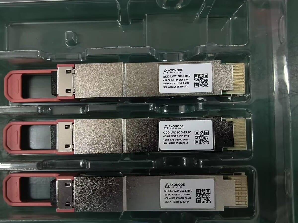
A US electric cooperative ISP used one QSFP-DD ER4 module at each endpoint. Below are the operator’s real FEC, BER, Rx power and temperature readings, shared with permission and with customer and site identifiers removed. View the Axonode 400G QSFP-DD ER4 40km optical transceiver.
One pluggable module at each endpoint over a single duplex dark-fiber span.
400G ER4 field results at a glance
| Metric | Captured result |
|---|---|
| Fiber route | 39.9 km dark fiber, single span |
| Link architecture | One QSFP-DD ER4 module at each endpoint |
| External optical equipment | No EDFA, DWDM shelf or transponder chassis |
| Link state | 400 Gb/s, up during the captured observation window |
| Uncorrected FEC codewords | 0 |
| CRC / FCS / symbol-error counters | 0 during the captured observation window |
| Pre-FEC BER | In the 10−6 range |
| Receive power | −14.5 to −13.1 dBm across the four optical channels |
| Module temperature | 36–45 °C across the captured readings |
These results show that this specific module pair, host configuration and fiber span established a clean 400G link at essentially the module’s stated reach. They should not be treated as a guarantee for every 40 km route: measured insertion loss, splices, connectors, fiber condition, host FEC and operating margin still have to be reviewed for each deployment.
Why this near-40 km result matters
Two details make the captured data especially useful for network teams evaluating long-reach 400G optics.
First, the readings were taken while the link was still on temporary patching. The operator had not yet completed final cleaning and acceptance testing because the fibers would be rerouted for production. The observed −14.5 dBm minimum therefore reflects the temporary state of the route. Cleaning and final routing may improve the reading, but only a post-move measurement can confirm the final margin.
Second, 39.9 km is effectively the full stated reach of this module. At that distance, the practical question is not simply whether the interface says “up.” Engineers also need to see whether receive power remains above the applicable threshold, whether pre-FEC BER stays within the correction capability and whether uncorrected codewords or packet errors appear.
In the captured output, uncorrected FEC codewords, CRC/FCS errors and symbol-error counters remained at zero.
What the operator reported
“Everything came up as expected. The Rx numbers are marginal but expected for 39.9 km—and it’s possible they will improve even more once the fibers are moved into production. Everything looks good on my end.”
How to read the FEC, Rx power and temperature data
1. Corrected FEC activity is not automatically a failure
Forward error correction is designed to correct errors before they reach the client traffic. On a long-reach PAM4 link, corrected codewords can be expected. The more important alarm condition is the appearance of uncorrected codewords or post-FEC packet errors. In this capture, uncorrected codewords remained at zero.
2. Pre-FEC BER provides an earlier view of link margin
The observed pre-FEC BER was in the 10−6 range. That is substantially below the error region normally associated with the limit of RS(544,514) correction. Trend data is still more useful than a single snapshot, so commissioning should record the value at both endpoints and monitor whether it changes after cleaning, rerouting or temperature variation.
3. DOM alarm threshold is not the same as guaranteed sensitivity
The four receive channels measured between −14.5 and −13.1 dBm and remained above the low-alarm threshold shown in the module’s DOM data. A programmed alarm threshold is an operational indicator; it should not be used as a substitute for the guaranteed receiver specification or a complete optical-loss calculation.
4. Temperature was normal in the captured state
Module readings of 36–45 °C were within the normal operating range for this deployment. Production acceptance should still consider the router’s airflow, ambient temperature and the higher power draw of long-reach 400G modules.
Why can a 400G ER4 module appear as LR4?
The operator noticed that the router displayed the optic as 400GBASE-LR4, even though the installed module was the 40 km-class ER4 option.
The displayed media name comes from the module application information that the host software reads and how that platform maps the code. A third-party long-reach module may use a compatibility profile recognized by the router, or the software may map an unfamiliar application to the nearest label it supports.
That display label does not, by itself, prove or disprove the module’s reach. Confirm the exact module part number, coding profile, optical specification, DOM readings and FEC performance instead.
If the displayed name matters for NMS inventory, audits or automation, share the router model, line card and OS release before the module is coded. Axonode can review the requested platform profile before shipment.
When a 40 km pluggable can simplify the network design
In this point-to-point deployment, a QSFP-DD module at each endpoint removed the need for a separate amplifier, DWDM shelf or transponder chassis. That can reduce rack space, power consumption and the number of active components at remote POPs, substations and huts.
It is a particularly useful architecture to evaluate for electric cooperatives, rural ISPs, WISPs and regional operators that have duplex dark fiber and need a straightforward 400G backhaul link. It is not the right architecture for every route.
| A direct 400G pluggable may fit when… | Review coherent or line-system options when… |
|---|---|
| The route is point-to-point over duplex single-mode dark fiber | The route exceeds the supported reach or loss budget |
| Measured insertion loss fits the module budget with engineering margin | Fiber loss, connector loss or repair margin is too high |
| Both hosts support the module, power draw and required FEC mode | The platform cannot supply the required power, cooling or FEC behavior |
| One 400G service is needed between two endpoints | Multiple wavelengths, ROADMs or flexible optical routing are required |
| Simpler remote-site operations are a priority | Fiber scarcity or future capacity favors a multiplexed line system |
For a more complete pre-deployment calculation, use the optical loss budget checklist for ISP backhaul links.
What to confirm before ordering 400G ER4 optics
Send these details before a sample or production order:
- Router or switch model, line card and port type
- Network OS and software release
- Route distance and measured end-to-end insertion loss
- Fiber type, connector count, splice count and passive components
- Required operating temperature and available airflow
- Any required NMS media label or OEM part-number match
Distance alone is not enough to approve a 40 km link. If measured loss is not yet available, Axonode can make a preliminary review, but the final recommendation should be confirmed against the route’s test data.
You can also use the optical transceiver compatibility checklist to prepare the host and software details.
Get the full test log or a module match for your span
The figures above are excerpts from a 12-page anonymized capture containing interface counters, PHY details, FEC statistics and per-channel DOM readings from both endpoints.
- Request the full 400G ER4 test log if you want to review the raw two-endpoint output.
- Request a 400G link review if you want us to check the module option, coding profile and expected Rx range for your route.
Frequently asked questions
-
Can a 400G QSFP-DD ER4 reach 40 km without an EDFA?
It did in this 39.9 km field deployment, using one module at each endpoint and no external amplifier. That does not mean every 40 km route will pass. The measured span loss, module specification, host FEC, connector and splice loss, fiber condition and engineering margin must all be checked.
-
Do corrected FEC codewords mean the 400G link is failing?
No. Corrected codewords show that FEC is doing its job. The more serious indicators are uncorrected codewords, post-FEC errors, CRC/FCS errors and a worsening pre-FEC BER trend. The captured deployment showed zero uncorrected FEC codewords.
-
Why might the router identify a 400G ER4 as LR4?
The host displays the application code it recognizes from the module and maps it according to its software. Compatibility coding or host software mapping can produce an LR4 label. Confirm the exact part number, coding profile, optical budget and measured performance instead of relying on the displayed label alone.
-
What Rx power should I expect near 40 km?
This deployment showed approximately −14.5 to −13.1 dBm across the four receive channels. It is a field reference, not a universal target. Your result will depend on the module specification and the route’s actual insertion loss, connector quality, splices and fiber condition.
-
What information is needed for a compatibility and link review?
At minimum, send the router or switch model, line card, OS version, route distance and measured insertion loss. Fiber details, passive components, temperature and required quantity help produce a more complete recommendation.
-
Are modules tested before shipment?
Yes. Axonode verifies the requested coding profile and performs routine module testing before shipment. Test evidence and DOM screenshots can be provided for long-reach sample evaluation when agreed as part of the order.