Optical Transceiver Compatibility Check: What to Prepare Before Ordering
Prepare the host, port, software, fiber and validation details needed for an optical transceiver compatibility check before requesting compatible optics.
Optical Transceiver Compatibility Check: What to Prepare Before Ordering
A useful optical transceiver compatibility check starts with the exact host, port, software, link and validation requirements. “10G SFP+,” “100G QSFP28” or “Cisco compatible” is not enough information for a defensible recommendation.
Before requesting compatible optics, identify the equipment at both ends, the installed software, the intended port configuration, the optical path and the evidence level you need. This allows an optics provider to assess the actual deployment rather than select a module from speed and form factor alone.
Why Optical Compatibility Checks Fail Before Ordering
Compatibility questions often arrive with only a brand, data rate or product family. Important details are discovered after the quotation—or after the modules reach the site.
Common information gaps include:
- The switch family is known, but the exact device or line-card model is missing.
- The port supports several speeds, but its intended operating mode is not stated.
- A QSFP port will be used for breakout, but the lane configuration and remote endpoints are unknown.
- The original equipment manufacturer (OEM) part number is missing from a replacement request.
- The module needs to be recognized by the host, but the software or firmware release is not recorded.
- Digital optical monitoring (DOM), also called digital diagnostic monitoring (DDM), is required, but nobody has confirmed how the host exposes it.
- The local optic is specified without the remote device, remote optic or fiber path.
- A request says “BiDi” without identifying the transmit and receive wavelengths at both ends.
These are not administrative details. They determine which product identity, coding profile, port settings and optical interface should be reviewed.
A shared form factor does not prove host acceptance. A matching connector does not prove the fiber path is suitable. Correct coding does not prove that traffic, monitoring and recovery behavior have been validated in the planned environment.
The Minimum Information Required for a Compatibility Review
Use the following intake tables before requesting an optical transceiver compatibility check. Some fields are always required; others apply only to particular hosts or link types.
Host information
| Information to provide | What to record and why it matters |
|---|---|
| Host vendor — required for each endpoint | Record the manufacturer of the switch, router, server adapter or other host. This identifies the relevant platform and coding context. |
| Device model — required for each endpoint | Record the complete chassis or fixed-system model. Compatibility may differ between devices from the same vendor. |
| Line card or NIC — conditional, but required when present | Record the exact line card, network interface card or adapter model. The port implementation may belong to the card rather than the chassis. |
| Software or firmware version — required when applicable | Record the current release and any planned upgrade version. Host recognition, port behavior and monitoring may depend on software. |
| Original OEM part number — strongly recommended for replacements | Record the full part number from the installed or approved module. This provides a controlled reference for an OEM replacement request. |
Port and application information
| Information to provide | What to record and why it matters |
|---|---|
| Port type — required | Record the physical cage and interface, such as SFP+, SFP28 or QSFP28. This confirms the mechanical and electrical interface under review. |
| Port speed — required | Record the intended configured rate, not only the port’s maximum rating. Multi-rate ports may need an explicit operating mode. |
| Breakout mode — required when breakout is used | Record the straight connection or breakout ratio, including both ends. This changes the application, lane mapping and remote-end requirements. |
| Lane configuration — conditional | Record the intended lane or application mapping. This is important for multi-lane and high-speed pluggable interfaces. |
| FEC requirements — conditional | Record the required or configured forward error correction mode. FEC expectations can affect whether a link operates as intended. |
| DOM/DDM requirements — conditional | Record required readings, alarms or operational visibility. Monitoring support and host behavior must be reviewed separately. |
Optical-link information
| Information to provide | What to record and why it matters |
|---|---|
| Fiber type — required | Record single-mode or multimode, including the known fiber grade. The optic must match the installed fiber plant. |
| Connector type — required | Record LC, MPO/MTP or another verified interface; include simplex/duplex and polarity where relevant. This prevents interface and polarity mismatches. |
| Distance and path — required | Record route distance, measured loss if available, and passive components. Nominal reach alone does not establish link feasibility. |
| Wavelength requirements — required when wavelength matters | Record the optical standard, wavelength or complementary BiDi directions. Both endpoints must have an optically valid relationship. |
The remote endpoint matters as much as the local one. For a mixed-vendor link, record the host and optic requirements for End A and End B separately. For a breakout assembly, identify every endpoint and lane rather than describing only the high-speed port.
If the request is part of a mixed bill of materials (BOM), add quantities by endpoint, intended site labels and the required coding profile for each line. This reduces the risk of correct modules being assigned to the wrong devices during staging.
Coding Is Only One Layer of Compatibility
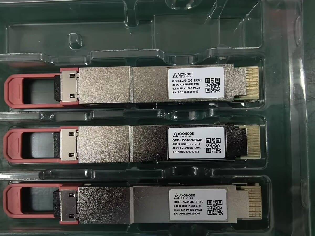
Transceiver coding controls identity and management information presented to a host. A suitable coding profile may help the host recognize and permit a third-party transceiver. That is important, but it is not the complete compatibility decision.
Coding support does not automatically verify:
- That the exact device, line card and software release have been tested together
- That the port is configured for the intended speed or application mode
- That breakout, lane mapping or FEC settings are correct
- That DOM/DDM readings and alarms behave as required
- That the optical interfaces at both ends are complementary
- That the real fiber path fits the transmit and receive power limits
- That the link remains stable under the customer’s traffic and operating conditions
This distinction is especially important for OEM replacement optics. A matching OEM reference can guide product identity and coding review, but it should not be treated as proof that every operating condition has been validated.
For an example of why host behavior can differ between platforms, see the Axonode guide on SFP behavior in MikroTik and Cisco environments. Use such scenarios to identify the questions that need investigation—not to infer support for another device or software release.
What DOM/DDM Can and Cannot Verify
DOM/DDM can provide operating information such as transmit power, receive power, temperature, supply voltage and laser bias current when those functions are supported and exposed by the host.
These readings can help with commissioning and fault isolation. For example, receive power can be compared with the approved limits for the exact module, and temperature or bias readings can help identify an abnormal operating condition.
However, readable DOM/DDM does not prove complete compatibility.
| DOM/DDM can help verify | DOM/DDM cannot prove by itself |
|---|---|
| The host can access supported diagnostic data | The coding profile is correct for every host function |
| Current optical power and operating readings | The link has adequate engineering margin over time |
| Whether a reading is inside the approved limit for the exact module | Traffic stability, error performance or recovery behavior |
| A baseline before and after a controlled change | Compatibility with another device or software release |
| Evidence for a broader troubleshooting process | Successful field operation in the final deployment |
Missing readings also need careful interpretation. They may relate to module capability, host support, coding, calibration, software behavior or how the platform presents diagnostics. Do not diagnose a failed module from missing DOM/DDM alone.
Compatibility Evidence Levels
The word “compatible” should be tied to the evidence available. The following levels answer different questions and should not be used interchangeably.
| Evidence level | Review boundary and appropriate outcome |
|---|---|
| Specification review | Establishes that the module identity and optical/electrical requirements appear suitable for the documented host, port and link. It does not establish host recognition or operational behavior. Outcome: candidate identified; continue compatibility review. |
| Coding verification | Establishes that a defined coding profile is available or has been checked against an approved source. It does not establish complete host behavior, traffic stability or field performance. Outcome: coding requirement recorded; validation scope still stated. |
| Controlled validation | Establishes that the intended module and host combination has been checked under documented test conditions. It does not cover every software release, topology or customer field condition. Outcome: state the exact tested configuration and limits. |
| Field validation | Establishes that the customer has confirmed operation in the actual device, software, fiber path and operating environment. It does not establish universal support outside that recorded deployment. Outcome: deployment-specific evidence only. |
Not every order requires every level. The appropriate level depends on the project risk, equipment environment, quantity, rollout method and evidence already available.
If only specification review and coding information are available, say so. If controlled validation is needed but no matching record exists, use a sample or pilot plan rather than upgrading the claim. Axonode should not present coding capability as laboratory or field validation unless the relevant evidence is documented.
Compatibility Review Workflow
A practical review moves from complete inputs to a bounded deployment decision:
This workflow is useful for a single replacement optic and for a multi-brand project BOM. It also creates a clear record of what was reviewed and what still depends on customer validation.
Compatibility is only one part of a complete optical-link decision. The 10G BiDi 40km deployment guide shows how host review sits alongside wavelength pairing and optical conditions. For broader route planning, see ISP/WISP backhaul optics.
Final Compatibility Checklist Before RFQ Submission
Copy this checklist into the request for quotation (RFQ) or attach it to the optics BOM.
Endpoint A
- Host vendor and complete device model
- Line card, NIC or adapter model where applicable
- Current software or firmware version
- Port identifier, form factor and configured speed
- Straight or breakout mode, lane configuration and FEC where applicable
- Original approved or installed OEM part number, if replacing a module
- Required coding profile and DOM/DDM behavior
Endpoint B
- Host vendor and complete device model
- Line card, NIC or adapter model where applicable
- Current software or firmware version
- Port identifier, form factor and configured speed
- Straight or breakout mode, lane configuration and FEC where applicable
- Existing or planned remote optic identity
- Required coding profile and DOM/DDM behavior
Optical path and project requirements
- Required data rate and optical application
- Fiber type and known grade
- Connector type, simplex/duplex arrangement and polarity where relevant
- Route distance and measured or estimated path loss
- Patch panels, splitters, MUX/DEMUX units or other passive components
- Required wavelength or complementary BiDi directions
- Quantity by endpoint and site label
- Required evidence level: review, coding verification, controlled validation or field pilot
- Sample quantity and rollout plan when validation is needed
For single-fiber projects, the BiDi optical transceiver collection provides product-family context. The exact wavelengths, product identity and host requirements still need to be matched for the planned link.
Frequently Asked Questions
Is the switch vendor and model enough for a compatibility check?
Usually not. Record the exact device model and, where applicable, the line card, NIC or adapter, software or firmware version, port type and intended port mode. The remote endpoint and optical-link requirements are also part of the review.
Why does the software or firmware version matter?
Host recognition, module policies, port behavior and diagnostic reporting can depend on the software environment. Record the current release and any planned upgrade version so the review is tied to a defined configuration.
Does correct transceiver coding guarantee that the link will work?
No. Coding is one compatibility layer. The deployment must still satisfy the port mode, speed, breakout or FEC requirements, optical interface, fiber path and operational validation appropriate to the project.
Does readable DOM/DDM prove that a transceiver is compatible?
No. It shows that supported diagnostic information is available through the host. DOM/DDM can help evaluate module and link conditions, but it does not prove traffic stability, recovery behavior or field operation in another configuration.
What should I provide when requesting OEM replacement optics?
Provide the complete original OEM part number, the host vendor and exact device or adapter model, software version, port configuration, remote-end optic and link requirements. A photo of the label or controlled command output may help identify the existing module, but the replacement still requires an evidence-scoped review.
What extra information is needed for breakout, BiDi or mixed-vendor links?
For breakout, record the ratio, lane mapping and every remote endpoint. For BiDi, record the complementary transmit and receive wavelengths at both ends. For mixed-vendor links, document the host, software, port and coding requirements for End A and End B separately.
When should a sample or pilot validation be requested?
Use a sample or pilot when the exact host/software combination lacks sufficient evidence, when the rollout risk or quantity justifies controlled verification, or when operational requirements such as monitoring and port behavior must be confirmed in the customer environment.
Prepare the Inputs Before Selecting the Optics
An optical transceiver compatibility check is only as reliable as the information behind it. Start with the exact equipment, port, software, original module and link requirements. Then match the product identity, review the coding and host constraints, and define additional validation where the evidence stops.
Need help reviewing compatible optics before ordering? Send Axonode the device models at both ends, line card or adapter details, software versions, port modes, original part numbers, fiber and connector information, distance or path loss, and the validation level your project requires.
Axonode can help organize the requirements, review the proposed optics BOM and coordinate a sample or pilot plan where needed. Compatibility should remain unconfirmed until the required evidence is available.